Call us now
07971191840
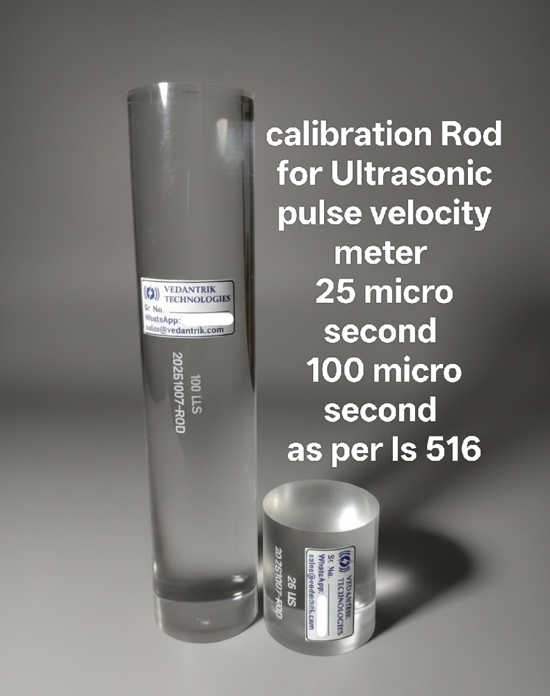

Calibration Rod for UPV:
Calibration rods used in the Ultrasonic Pulse Velocity (UPV) test is a crucial tool to ensure that the readings obtained from concrete specimens are accurate and reliable. According to IS 516 (Part 5/Sec 1): 2018, the calibration of the UPV apparatus is performed using standard calibration rods of known lengths and material properties. These rods are made of a homogeneous, dense, and isotropic material, whose Ultrasonic pulse velocity values are well established. The calibration process generally involves the use of two standard rods, where the first rod labeled 25 s, is used for initial calibration of the equipment. The second rod labeled 100 s is then used to verify the accuracy of calibration. By checking the transit time through this 100 s rod, engineers can confirm whether the equipment remains correctly calibrated across a wider range of travel time.
During calibration, the transmitting and receiving transducers are placed at the two ends of the calibration rod using a coupling medium such as grease or petroleum jelly to remove any air pockets that may tamper with the actual results and to also ensure good acoustic contact. A pulse is then transmitted through the rod, and the transit time is recorded, this mode of operation is called through transmission mode. Furthermore, the time measurement is then verified with reference time labeled on the rods to confirm the calibration.
This dual-rod system (25 s and 100 s) ensures that the UPV equipment is not only initially calibrated but also verified for linearity and consistency over different travel times. It confirms that the instruments internal timing circuit and transducers function correctly across the expected range of measurements. As per IS 516 (Part 5/Sec 1): 2018, such calibration and verification must be performed before and after each series of tests, or whenever there is any suspicion of instrument drift or malfunction.
Purpose of Calibration Rod:
To ensure measurement reliability Calibration rods ensure that subsequent UPV readings on concrete are valid and dependable.
To check equipment accuracy Ensures the UPV apparatus gives correct time readings before testing concrete.
To detect instrument errors Identifies any malfunction or timing error in the transducers or electronic timer.
Principle:
The use of calibration rods in UPV testing is fundamentally based on the principle of elastic wave propagation through homogeneous and isotropic media. The calibration rod serves as an excellent reference medium, having well characterized elastic and geometric properties, which allows for consistent verification of accurate time measurement capability of the UPV instrument. They behave like an idealized medium for propagation, with minimal internal scattering, negligible attenuation, and uniform acoustic impedance. When an ultrasonic pulse is transmitted through the rod, the longitudinal wave propagates along a predictable path, and the received signal exhibits well-defined wavefront characteristics. Since the UPV technique determines the pulse velocity V from the ratio of the known path length L to the measured transit time T (i.e., V=L/T), the accuracy of velocity calculation critically depends on the precision of time measurement and the stability of the transducerinstrument system. Any systematic deviation in the time registration or transducer response will introduce errors in the final velocity calculation, which can lead to misinterpretation of concrete quality and durability. Therefore, the calibration rod provides a standard benchmark against which such instrumental deviations can be identified and corrected.
Components:
Reference Rod (25 s): Used to establish a standard calibration range for the accuracy of time measurement in the UPV apparatus.
Reference Rod (100 s): Utilized to confirm the validity and consistency of calibration across a longer propagation path length.
Standard Procedure: Overview
Inspect the UPV instrument, ensuring all components are functional. Select clean reference bars, typically short (25s) and long (100s), free of surface defects.
Apply an appropriate coupling agent (e.g., petroleum jelly or glycerol paste) to the transducer faces and bar surfaces to ensure efficient ultrasonic energy transfer and prevent signal distortion.
Place the transducers on the short reference bar and measure the transit time. Compare with the known value (25s); any deviation beyond 0.5% indicates the need for adjustment.
Repeat the measurement on the long reference bar (100s) to confirm linearity and consistency across longer path lengths.
If both measurements fall within tolerances, the instrument is calibrated and ready for field testing. Any discrepancies must be corrected before concrete testing.
Factors influencing the Calibration Process:
Instrument Accuracy and Stability: The electronic timing system, pulse transmitter and the receiver must be stable and precise. Any drift or noise in the electronics can affect the measured transit time,leading to calibration error.
Transducer performance: Variation in transducer sensitivity, frequency , or wear can influence pulse generation and reception, affecting the measured time. Calibration ensures these effects are accounted for.
Coupling Quality: The efficiency of energy transfer between transducer and calibration rod and uniformity of the coupling agent. Poor coupling can reduce signal amplitude or introduce timing errors.
Transducer Alignment and Pressure: Misalignment or inconsistent contact pressure can change the effective path of the pulse, introducing errors in timing measurement during calibration.

Price:

 Get Latest Price
 Send Inquiry
 Send SMS